Mobile transformer high voltage
I. The permanent magnet high-voltage vacuum switch for KJG-400/6Y, KJG-400/10Y series flameproof and intrinsically safe mobile substation for mining is mainly used at the low voltage side of the explosion-proof mobile substation for mining with rated voltage of 6(10) KV, rated frequency of 50Hz, rated current to 400A and three-phase AC neutral point not directly grounded and is matched with the low-voltage protection box for BXJ series flameproof and intrinsically safe mobile substation for mining manufactured by our plant. It controls the mobile substation, infrequent make-break operation is implemented, and it has short circuit, overload, overvoltage, under-voltage, phase failure transformer over-temperature, and other protection functions.
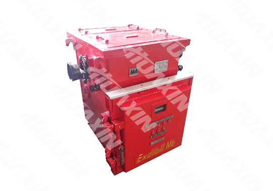
1. Technical parameters
1) Short-circuit breaking and making current frequency: 'break - 180s - make-break - 180s, make-break' for 12 times, break for 4 times, make-break for 8 times;
2) Rated short-circuit breaking current (effective value of AC component): 12.5A;
3) Rated short-circuit making current (peak value): 31.5kA
4) Rated short-circuit duration: 2s;
5) Rated short-circuit breaking current times: 30 times;
6) Mechanical life of the circuit breaker: 10,000 times;
7) Main electrical and mechanical characteristics:
a. Contact break distance: 9±1 mm
b. Contact overtravel: mm
c. Average closing speed: 0.6 to 1.3 m/s
d. Average opening speed: 0.8 to 1.5 m/s
e. Contact closing and opening non-synchronism: ≤1.2 ms
f. Contact bounce time at closing ≤3 ms
8) For rated insulation level, see Table 1
Table 1
Rated
voltage
Short-time (1min) industrial frequency withstand voltage value (effective value) KV
Remarks
Phase-to-ground, phase-to-phase, between open contacts of the circuit breaker
Between open contacts of the isolating switch
Secondary circuit to ground
The voltmeter, display device and so on shall be disconnected for secondary circuit voltage resistance
6
23
26
2
10
30
34
2
Rated full wave lightning impulse withstand voltage (peak value) KV
Phase-to-ground, phase-to-phase, between open contacts of the circuit breaker
Between open contacts of the isolating switch
6
40
46
10
60
70
9) For voltage class, electrical clearance and creepage distance, see Table 2Table 2:
Rated voltage
Minimum electric clearance mm
Minimum creepage distance mm
100
2.5
4
6000
60
100
10000
100
160
2. Protection feature
1) Overvoltage and under-voltage protection
When the line voltage ≥115%Ur, the overvoltage signal is sent (overvoltage setting range 100∽130%); when the line voltage ≤75%Ur, the under-voltage is sent (under-voltage setting range 60∽100%); after the signal is sent, the circuit breaker shall be opened with time delay, and the time delay setting range is 5∽65S.
2) Short circuit protection
The short-circuit current setting value is set according to the times of the rated current value (3 to 10 times). When the short-circuit current is 1.2 times of the setting value, the action time is not larger than 0.1s, and error between the action value and the setting value shall not be larger than ±10%.
3) Overload protection
The overcurrent setting value is set according to times of the rated current value, and inverse time limit features between the action time and the overload current is shown in the following table.
Test current / current setting value
Action time S
State
<1.05
No action
Cold condition
1.2
<120
Hot condition
1.5
<60
Hot condition
2.0
<20
Hot condition
6
Backward time >8
Cold condition
4) Overtemperature protection
When the dry transformer of the mobile substation reaches the protection temperature, the switch can be opened.
5) Phase failure protection
The three-phase failure protection action features shall conform to provisions in the following table
Group
Action boundary
Action time
Initial state
Pa
A phase is zero
The other two phases are 1.05 times of the setting current
<20
Hot condition
Pb
Any two phases are connected with the rated current, and the other phase is connected with 0.9 times of the rated current
No action for a long term
Cold condition
6) Self-inspection function
Overload and short circuit protection can be subject to self-inspection with the button.
1 It is matched with the transformer and low-voltage protection box to jointly constitute the operation mode of high voltage side circuit breaker of the internationally advanced low voltage side failure break transformer.
2 The intelligent single chip microcomputer controller and man-machine screen (LCD and operation keyboard) system with advanced technologies are adopted: high sampling precision, strong interference immunity, flexible and reliably action performance, stable quality, flexible and convenient parameter setting, intuitive and simple operation and failure screen.
3 It has the unique high-voltage isolating switch chamber with safe and reliable operation and maintenance.
4 The intelligent integrated protector is provided with system self-inspection. Failure diagnosis inspection and memory function can conduct real-time detection and digital display of the operating state and failure indication, so as to facilitate system use. Maintenance and failure diagnosis.
5 Complete protection function: it has overload, short circuit, overvoltage, under-voltage, emergency stop, phase failure, backup trip and other protection, and can conduct reliable break of the failure signal from the low-voltage protection box. The intrinsically safe circuit is utilized to realize safer and more reliable remote operation.
6 The permanent magnet mechanism opening and spring opening are combined, so thatt distribution of the opening spring is more ideal. Compared with the circuit breaker of the spring operation mechanism, the movable components are greatly reduced, so that reliability and mechanical life are substantially improved.
7 The operation loop supply transformer is universal for 10kV and 6kV.
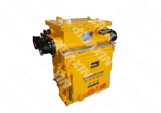
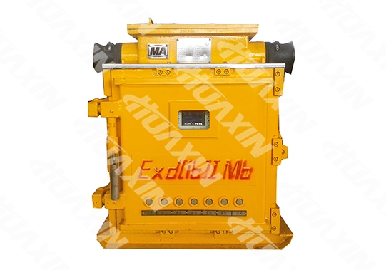
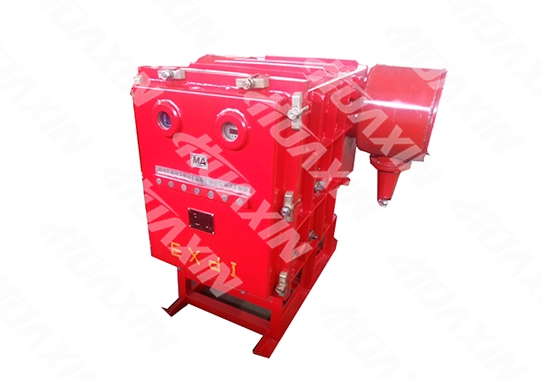
1. The distribution switch mainly consists of the explosion-proof shell, ZN□-12/Y630 vacuum permanent magnet mechanism circuit breaker and wiring chamber (see Figure I, II and III).
2. Explosion-proof shell: it consists of the main body, front door and wiring chamber, the front door is of the quick open structure, and the front is arranged with start, stop, resetting, emergency stop, displacement, confirm and adjustment button as well as the display part.
The right side is arranged with the electrical locking device, manual (test) closing device, body propulsion mechanism handle, stop button (machinery) and observation window, and the upper is arranged with the explosion-proof wiring chamber.
The right is also arranged with the door opening safety locking device: before the door is opened, the distribution switch is automatically opened.
3. ZN口-12/Y630 high-voltage vacuum permanent magnet circuit breaker (see Figure IV) is applicable for the indoor 6kV, 10Kv/50Hz three-phase AC power supply system. It is suitable for indoor high-voltage power distribution system, and can conduct frequent operation or multiple breaking short-circuit current within the range of rated current. The permanent magnet circuit breaker has the significant features of small volume, light weight, simple structure, reliable operation, maintenance free, long service life and so on, and is the ideal next-generation product for mechanical operating mechanism.
4. The lead-in cable of the pressure plate type lead-in device for the wiring chamber lead the power supply into the main chamber through the insulating sleeve type terminal.
5. Connection mode of the high-voltage vacuum switch and interlocking line of BXB low-voltage protection box:
(1) The dry transformer manufactured by the company can be connected with the built-in connecting line of the transformer directly.
(2) The dry transformer manufactured by other plants are connected with the low voltage side through the seven-core wiring terminal of the wiring chamber and the compression nut type cable lead-in device.
6. The vacuum switch has the manual (test) closing function.
The 'manual (test) closing' function of the switch is taken as the backup for normal electric closing for emergency test closing when the power supply side and load side of the mobile substation are at the normal state, there is failure in the electric closing system, and it cannot be normally closed. The specific operation steps are as follows:
After it is confirmed that there is no failure indicated on the display screen at the high and low voltage sides of the mobile transformer, if the switch cannot be normally closed when the closing button at the high and low voltage sides are pressed, it indicates failure in the switch closing system components. At the moment, open the front door, turn the toggle switch at the right side of the circuit breaker to the 'manual' side, close the front door, conduct operation according to the labeling direction of the manual closing device at the right of the high-voltage switch, and test closing. Turn the toggle switch to the side of 'electric' after fault handling, and recover normal electric closing!
Our offering
Case studies
Contact information
-
About Huaxin
-
Follow us
-
Share us
©1996-2017 晉ICP備07500050號 Huaxin Copyright
©2016-2017 晉ICP備07500050號 Huaxin Copyright


